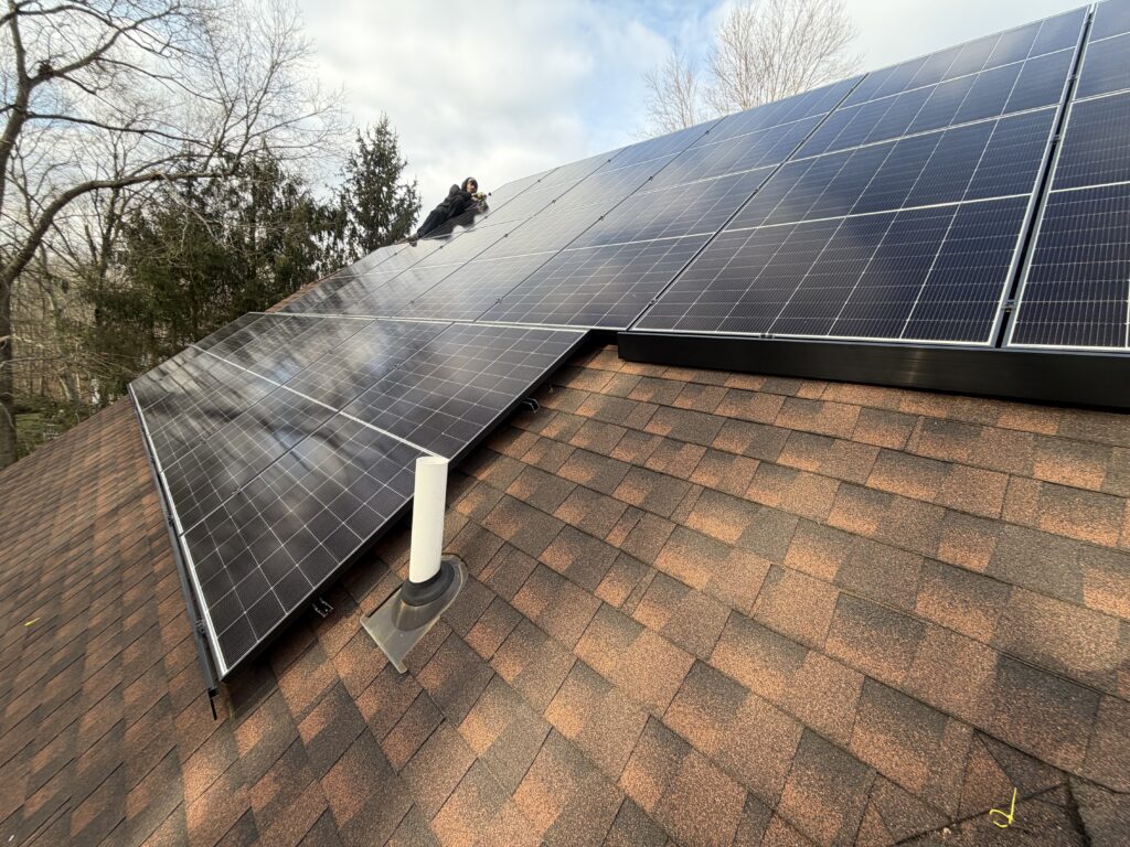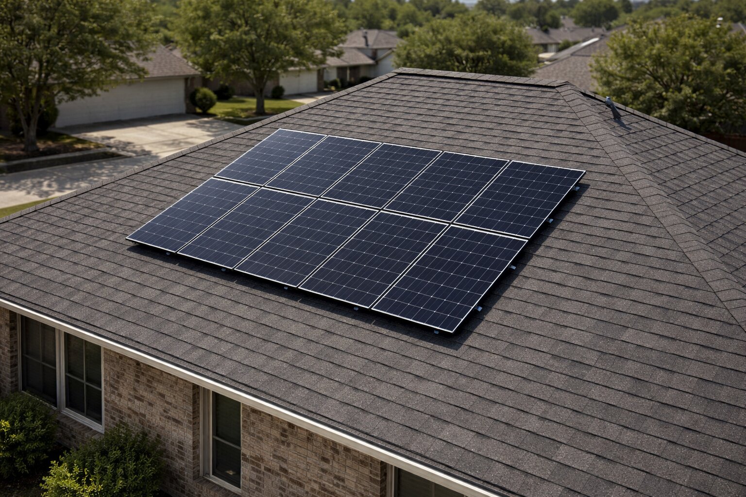
Solar attachment spacing ASCE 7-22 governs how often you fasten modules on comp-shingle rooftops. It’s driven by wind pressures, roof zones, and the allowable withdrawal of your listed fasteners.
This field guide is written for plan-set drafters and engineers who need clear, citable steps that pass AHJ review. It prioritizes TRT01 (rail-less comp-shingle) and TRT02 (rail comp-shingle) and points to our internal span tables and PE letters.
| TL;DRShow the roof zones. Under ASCE 7-22 Components & Cladding, pitched roofs are divided into Zone 1 (field), Zone 2 (edge), and Zone 3 (corner). Corners and edges typically require tighter spacing than the field. Document inputs right on the drawing: basic wind speed (Vult), exposure category, mean roof height, roof type and slope, zone width “a”, effective wind area (tributary area per attachment), and the specific TRT system/listing. Select spacing from the correct state and code-cycle PE tables for TRT01 or TRT02. Reference the table ID and page in your Attachment Schedule. Re-check spacing whenever site or layout inputs change. Orientation, exposure, slope, height, wind speed, or code cycle changes require a new selection from the PE tables or a stamped calc update. |
For background on how wind drives zonal spacing, see wind load design for solar mounting.
Why ASCE Roof Zones Drive Attachment Density
Wind uplift is not uniform. It peaks at corners, is elevated along perimeters, and is lowest in the field. ASCE 7-22 formalizes this zoning so designers and authorities have a consistent language for where attachments must be closer together.
For typical residential gable and hip roofs within the Chapter 30 limits, standard zone diagrams apply and are expected in the plan set. In practice, this means your Attachment Schedule will nearly always specify three spacings, one for each zone, selected from the appropriate PE-stamped span tables.
The Inputs You Must Put On The Plans
Create one clearly labeled Wind & Attachment Inputs box on the permit sheets. Reviewers should not have to infer or hunt for any variable.
- Basic wind speed (Vult, mph). From the ASCE Hazard Tool or the adopted map for the jurisdiction. Include site coordinates if required.
- Risk category. Residential rooftops are typically Risk Category II under IBC Section 1604.5.
- Exposure category (B, C, or D). Describe terrain in one line (e.g., “suburban with numerous two-story structures” for B; “open terrain/airfield” for C; “coastal with long fetch” for D).
- Mean roof height (ft). Measured per ASCE definitions. Many residential projects fall at or below 60 ft.
- Roof type and slope. Gable vs. hip and the pitch determine which table applies in the PE sets.
- Zone width “a.” Dimension the width of edge strips and size of corner squares on the roof plan; label Zones 1/2/3.
- Effective wind area (EWA). The tributary area per attachment based on layout and orientation.
- System and listing. Identify TRT01 or TRT02 and include the relevant UL 2703 pages used as the basis for allowable withdrawal and embedment.
Putting all of this in one place speeds review, reduces redlines, and keeps submittals consistent across offices.
Plan-Set Structure That Passes Review
Sheet A1 – Cover & Code Notes
- Project address and coordinates
- Adopted codes (IBC/IRC year, ASCE 7-22, NEC year)
- Note: “Attachment spacing per TRT PE-stamped span tables (state set, rev/date).”
Sheet A2 – Roof Plan & Zoning
- Scaled roof plan with dimensioned a at eaves and rakes
- Clear hatching/labels for Zone 1, Zone 2, Zone 3
- Major discontinuities (hips, valleys, dormers) shown where they affect zoning or layout
Sheet A3 – Attachment Schedule & Inputs
- Attachment Schedule listing spacing for Zones 1/2/3 and table ID/page
- Wind & Attachment Inputs box with all variables from the list above
Sheet A4 – Details & Listings
- TRT01/TRT02 attachment details (flashing, sealing, embedment notes)
- Highlighted UL 2703 pages used in design
- Electrical context: method/listings for NEC 690.12 rapid shutdown (if shown on the same package).
If your jurisdiction is strict on documentation formatting, this overview helps you pre-answer common reviewer notes: avoid solar permit rejection: a field guide.
This layout pre-answers AHJ questions on zones, exposure, and listings.
Spacing Selection Workflow (TRT01/TRT02 on Comp-Shingle)
- Confirm site conditions. Verify Vult, exposure, mean roof height, roof type, and slope match jurisdictional requirements and the latest site information.
- Finalize layout. Decide orientation (portrait/landscape), number of attachment rows, rail vs. rail-less, and any shared-rail strategies. These choices set the tributary area per attachment.
- Mark roof zones on the plan. Dimension a and label Zone 1/2/3.
- Open the correct PE-stamped span tables. Use the state and code-cycle set corresponding to the project jurisdiction; confirm revision date.
- Select spacing for each zone. Choose Zone 1/2/3 values that match the documented inputs and the TRT system/listing.
- Record the source. In the Attachment Schedule, list table ID, page, and revision/date.
- Package support documents. Attach the wind/exposure documentation and the UL 2703 pages referenced.
The outcome is a simple three-line schedule on the plan, Field / Edge / Corner, fully traceable to the PE tables.
Triggers That Require Re-Selecting Spacing
Attachment spacing is sensitive to changes in site assumptions and layout. Re-select from the PE tables and update the schedule when any of the following occur:
- Module orientation change (portrait ↔ landscape). Alters tributary area and may change the effective wind-area band used in the tables.
- Exposure reclassification. If the AHJ classifies the site as C rather than B, expect tighter spacing at the perimeter and corners.
- Roof slope or height change. Updated measurements can move the design into a different table within the set.
- Jurisdiction wind-speed update. If the adopted Vult or map reference changes, spacing must be re-selected.
- Code-cycle change. Moving from ASCE 7-16 references to ASCE 7-22 requires the matching state set.
- Layout adjustments. Larger modules, different rail spacing, shared-rail decisions, or added obstructions can affect tributary areas and zoning.
Common AHJ Comments and How to Address Them
“Show roof zones with dimensions.”
Provide a scaled plan with dimensioned a, and label Zones 1, 2, and 3. Cite the figure/table reference used for zoning.
“Provide wind speed and exposure basis.”
Include the ASCE Hazard Tool printout or adopted map excerpt, and add a one-line exposure narrative with surrounding terrain/obstructions. Include the ASCE Hazard Tool printout or adopted map excerpt, and add a short exposure narrative.
For context on how these inputs drive attachment density, review wind load design for solar mounting.
“Identify the product listing and embedment.”
Attach the UL 2703 evaluation pages for TRT01/TRT02. Call out minimum embedment and compatible framing in the detail or general notes.
“Explain changes after layout.”
When orientation or exposure changes, note the reason, update tributary area/EWA as applicable, and list the new table ID/page in the Attachment Schedule.
“What about gravity and seismic?”
Indicate that gravity combinations and seismic checks are reviewed in the structural package, while the governing case for comp-shingle attachments is typically wind uplift. Reference where that review resides (e.g., separate calcs packet or the PE table basis).
TRT01 / TRT02 at a Glance (Comp-Shingle)
TRT01 Rail-less (Composition Shingle)
- Listing: UL 2703 recognizes array-level PV hazard-control solutions compatible with rapid-shutdown compliance.
- Fit: 30 – 40 mm module frames.
- Highlights: Base + mini-rail integrated design; adjustable height to accommodate shingle undulations; double-butyl base seal; universal mid and hidden end clamps for a clean finish.
- Typical layout practice: Two attachment rows per portrait module; perimeter/corner spacing per the PE tables; field spacing per the same set.
TRT02 Rail (Composition Shingle)
- Listing: UL 2703; compatible with 2023 NEC 690.12 rapid shutdown methods when paired appropriately.
- Fit: Module frames ≥ 30 mm; supports skirts and shared-rail strategies.
- Highlights: Rails distribute gravity loads; uplift checks and spacing still follow the same zoning logic and PE tables.
- Typical layout practice: Match perimeter/corner spacing to the zone requirements; field spacing may be larger within table limits.
Product selection determines installation method and aesthetics. Attachment spacing remains a function of roof zone + documented inputs + PE table selection.
Coordination Tips For EPCs and Install Crews
- Lock inputs early. Confirm Vult, exposure, slope, and mean roof height at proposal or site-survey stage to avoid redesign during permitting.
- Standardize orientation by market. If crews prefer portrait in one market and landscape in another, build two base templates with pre-filled Inputs boxes to reduce errors.
- Photograph rafters and sheathing. Clear framing photos and measurements support embedment and substrate notes referenced in the listing.
- Train on zone recognition. Field teams should know what “edge” and “corner” mean at the roof so they can spot conflicts with obstructions, hips, and valleys before installation day.
- Keep PE table sets current. Use the latest state set, ASCE 7-22, rev/date. Archive superseded sets to prevent accidental use.
Download: Spacing Cheat Sheet + Stamped Calcs Request
The one-page cheat sheet mirrors this workflow and includes fill-in fields for Vult, Exposure, h, slope, EWA, GCp source, and TRT allowable. Use it with our PE-letter span tables by state (ASCE 7-16 and 7-22 sets) accessible through the customer portal.
Download the Spacing Cheat Sheet (free)
Request Stamped Calcs for Your Project
Standardizing inputs on one sheet keeps your submittals consistent across offices and jurisdictions.
FAQs
Does exposure category change the fastener selection?
Exposure does not change the product listing itself, but it affects the design basis reflected in the span tables. Sites classified as C or D commonly require tighter spacing than B for the same roof and module layout.
What happens if module orientation changes?
Orientation changes tributary area per attachment and sometimes EWA band selection. Recalculate uplift using the new tributary areas, then compare to the same UL allowable and revise spacing accordingly.
Do comp-shingle fastener specs change with exposure category?
The product listing stays the same, but the site exposure affects the design basis reflected in the span tables. Sites classified as C or D commonly require closer spacing than B.
Compliance & Contact
Standards referenced: ASCE 7-22 Chapters 26 – 30 (Components and Cladding), UL 2703 (Mounting Systems).
Electrical context: 2023 NEC 690.12 rapid shutdown applies to roof-mounted PV; verify method and listings in the electrical package.
Top Rack Technology, Inc. – Manufacturer of solar racking systems
www.topracktech.com | info@topracktech.com | 888-575-7818