A solar mounting structure is the foundation of every rooftop and ground-mounted solar array. Choose the wrong one and you face permit rejections, roof damage, and callbacks that cost more than the install.
Choose the right one and the system goes up fast, passes inspection the first time, and performs reliably for 25 years or more. This guide covers the main structure types, how to match them to roof and site conditions, and what certified systems look like in the field.
Why the Mounting Structure Matters More Than Most Installers Realize
Panels get all the attention, but the mounting structure carries all the risk. It transfers every wind uplift force, every snow load, and every thermal expansion cycle directly into the roof or ground. A panel that underperforms costs you energy output. A mounting structure that fails costs you the roof, the warranty, and the customer relationship.
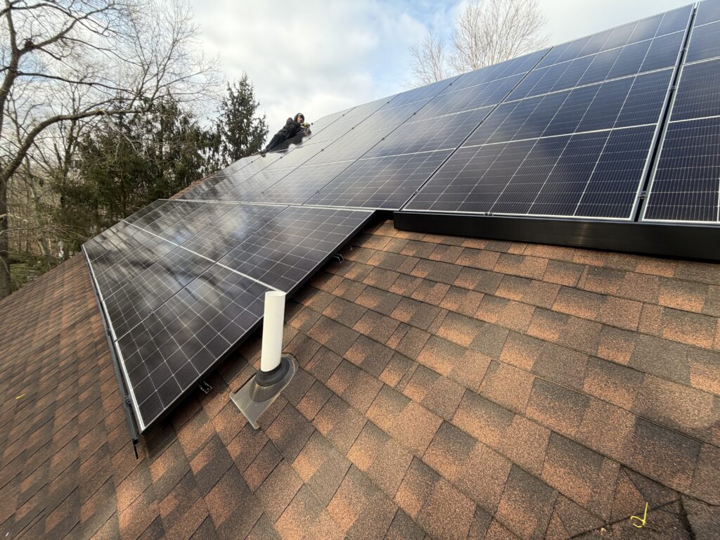
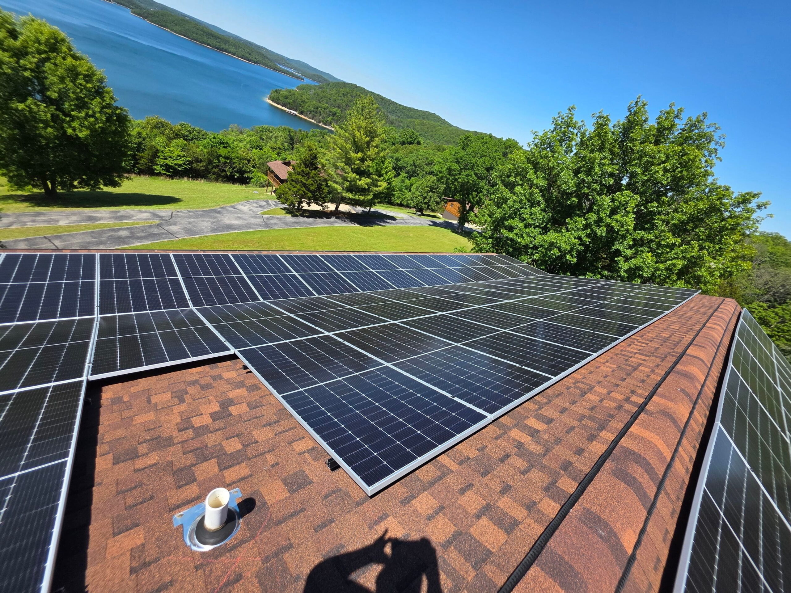
For composition shingle roofs specifically, the structure must work with the shingle’s lap and drainage design, not against it.
Every penetration point is a potential leak if the base is not seated correctly and sealed with a compatible sealant. That is why system selection starts with roof type, not panel brand.
Types of Solar Mounting Structures
Rail-Based Roof Mount
Rail-based systems use horizontal aluminum rails attached to the roof structure via bases. Panels clamp onto the rails, giving installers flexibility in panel positioning and layout adjustments. Rail-based systems are used across many roof types when paired with the correct attachment. TRT02 specifically applies to composition shingle roofs, while TRT03 uses tile hooks for tile roofs.
The TRT Rail Base System (TRT02) is built for composition shingle roofs where rail support improves load distribution across the array. TRT02 is UL 2703 listed and uses integrated bonding features through approved clamps and grounding components. Installers should follow the TRT installation manual for required grounding lugs, bonding jumpers, and grounding conductors.
For base spacing on TRT02, always reference TRT’s PE-certified span tables rather than field estimates.
Rail-Less Roof Mount
Rail-less systems eliminate the rail entirely. TRT01 bases attach according to the approved layout and installation manual, with fastening conditions varying depending on whether the base aligns with rafters or deck. Panels connect to the bases through a direct-mount interface. Fewer components mean faster installs, lower material costs, and reduced uplift exposure since there is no rail gap for wind to catch.
The TRT Rail-less Base System (TRT01) is designed specifically for composition shingle roofs. TRT01 is designed for simplified fastening with 5/16″ x 3″ lag screws. Installers should follow the TRT installation manual, PE letters, and local AHJ requirements for drilling or pilot hole practices. TRT01 uses an integrated butyl sealing approach. For flat shingle areas, additional sealant may not be required. Where the manual calls for it, such as keyway conditions or shingle-layer transitions, only approved sealants should be used. Silicone-based sealants or lubricants should never be used with butyl.
Tile Roof Mount
Tile roofs require a different approach because the tile itself cannot carry attachment loads the way shingles or decking can. TRT03 tile hooks are installed under the tile and fastened into the roof framing member using the specified screws or lag bolts, with sealant and sealing washers as required by the manual.
TRT03 is designed to preserve the tile roof’s water management function, but tiles may need to be removed, adjusted, or notched according to the installation manual to ensure proper fit around the hook.
Ground Mount
Ground-mounted structures sit on steel frames driven or anchored into the ground. Fixed-tilt ground mounts set panels at a single optimized angle for the site’s latitude. Adjustable systems allow seasonal tilt changes for better year-round output.
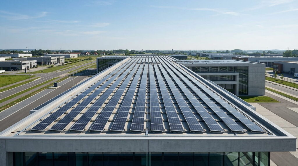
Ground mounts are common on commercial and utility-scale projects where roof space is limited or roof conditions are not suitable for penetration-based systems. They require geotechnical review of soil conditions and local permitting for foundation design. Wind and ballast calculations are critical for these systems, per ASCE 7 guidelines.
Ballasted Flat Roof Mount
Ballasted systems use concrete blocks or weighted bases to hold the array in place without roof penetrations. They are popular on commercial flat roofs where penetrations are not permitted or where the roof membrane is too new to disturb.
Wind and ballast calculations are critical for these systems. Uplift forces on flat roofs can be significant, and the ballast weight must be engineered to match the specific wind exposure category of the site.
How to Match the Structure to the Roof and Site
The selection process comes down to four inputs: roof type, local wind speed, ground snow load, and panel layout. Once you have those, the system type and base spacing follow from certified documentation rather than field judgment.
For composition shingle roofs, TRT01 and TRT02 cover the two main configurations: rail-less for fast lightweight installs and rail-based for heavier arrays or layouts that benefit from rail flexibility. For tile roofs, TRT03 provides the hook interface. For ground and flat roof applications, the structure type depends on site conditions and local code requirements.
Understanding how wind and snow loads shape these decisions is covered in detail in the solar mounting wind load and snow load guide, which walks through exposure categories, load factors, and what certified ratings mean in practice.
| System | Max Panel Size | Mid Clamp Frame Height | Skirt Clamp Frame Height |
| TRT01 | Less than 2278 mm x 1134 mm | 26-37 mm | 26-40 mm |
| TRT02 / TRT03 | Less than 1722 mm x 1134 mm | 26-37 mm | 26-40 mm |
What Certified Means and Why It Matters at Permit
A certified solar mounting structure carries tested ratings for wind uplift, snow load, fire classification, and electrical bonding. For rooftop systems in the US, UL 2703 is the standard that ties bonding, grounding, and fire class together into a single listing.
When you submit plans with a UL 2703 listed system, the reviewer sees a listing matrix that confirms your exact module and racking combination has been tested as a unit. That single document answers most of what AHJs ask about bonding and fire performance. Missing it is one of the most common reasons plan sets get kicked back on first review.
TRT01, TRT02, and TRT03 are all UL 2703 listed. TRT01 and TRT02 also include ASTM D7147 and TAS 100(A) testing for uplift, shear load, water penetration, and Florida high-wind applications.
Bonding is supported through approved clamps, lugs, and bonding components. Installers must still follow the manual and project electrical design for grounding conductors, bonding jumpers, and documentation.
For a full breakdown of what to include in your submittal package, the UL 2703 solar mounting guide covers listing matrices, compliance letters, and fire class statements in detail.
Installation Factors That Determine Long-Term Performance
The best solar mounting structure on paper still fails if installation steps are skipped or rushed. The factors that matter most are base seating, sealant compatibility, torque consistency, and documentation.
For TRT01 and TRT02 on composition shingle roofs, bases must sit flat with full contact and no trapped granules.
Hardware should be tightened to the torque values specified in the TRT installation manual and any project-specific approved documentation.
Following the correct seating, sealant, and torque steps is what separates a system that passes inspection and performs for 25 years from one that generates callbacks in year two.
Choosing the Right System for Your Next Project
Start with your jurisdiction’s wind speed and snow load requirements. Check the roof type and age. Select a system with certified ratings that match those requirements and reference TRT’s PE-certified span tables for base spacing. Submit complete documentation with your plan set.