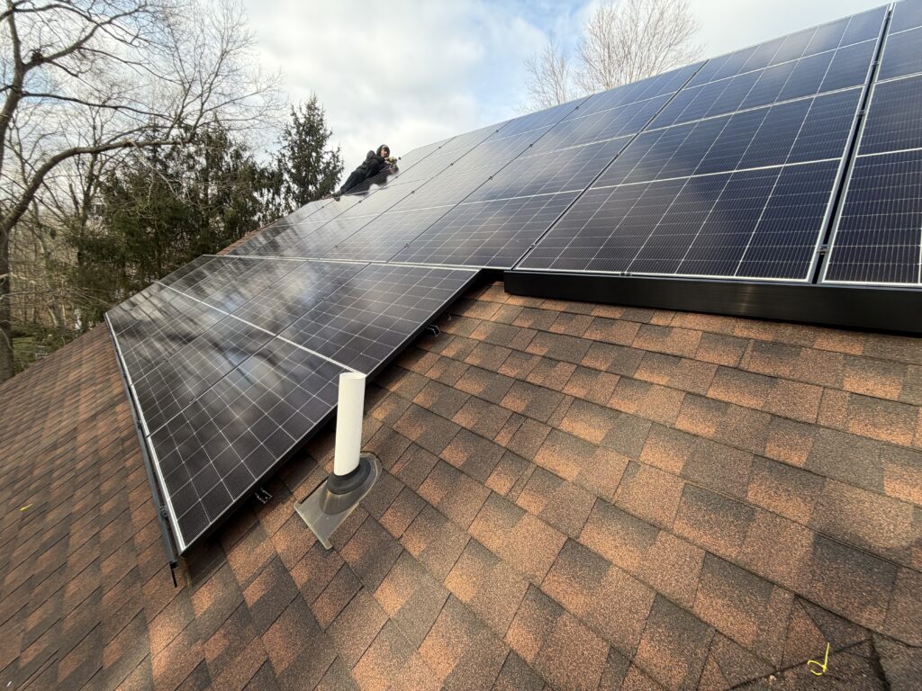
This section builds on Part 1 (Installation Site Preparation) and Part 2 (Span Table Selection) and explains how to perform span table application using a real project example from start to finish. It shows installers how to read the table accurately, match the correct parameters, and understand why a specific maximum span value is chosen. Once this span is identified, the installer can confirm whether the bracket spacing is suitable for the selected solar module and roof configuration.
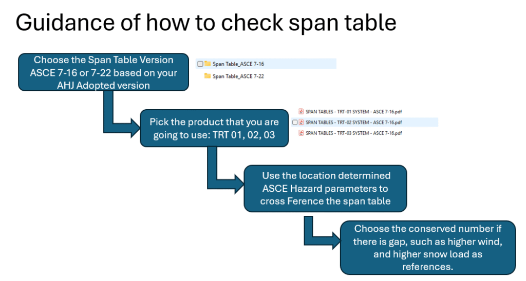
Example: TRT 01 Rail-less System
Since TRT 01 is a rail-less system, the Bracket (Base) always mounts to the long side of the solar module. This means the installer must check whether the width of the solar panel is smaller than the maximum allowable span listed for the project location.
Project Information
- Location: 1536 E 75th St, Los Angeles, CA 90001
- Roof Type: Gable roof
- Mounting Method: Truss
- Roof Pitch: Between 14-18 degrees (using 14 degrees as a conservative value)
- Module: Q.PEAK DUO BLK ML-G10+ 415
- Length 67.7 in × Width 44.1 in
- Module Area: 2985.57 in² = 20.73 ft²
- Product: TRT 01 Rail-less System
- Code Used in California: ASCE 7-16
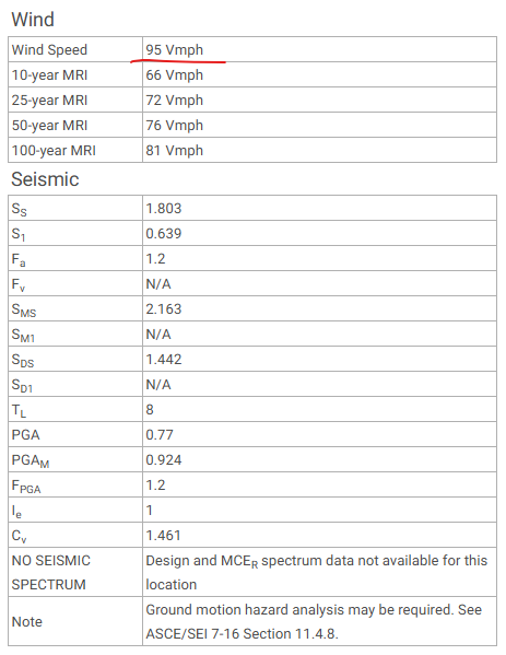
- Hazard Values: Retrieved from ASCEHazardTool.org
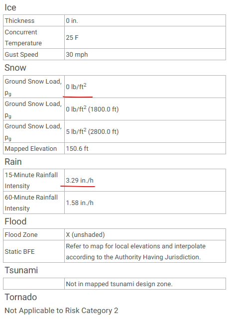
Step 1 – Open the Correct Span Table
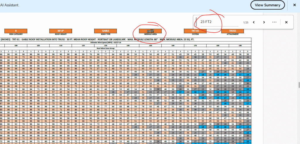
Search for “SPAN TABLES – TRT-01 SYSTEM – ASCE 7-16”.
Because the module area is 20.73 ft², it falls between 19 ft² and 23 ft².
To ensure safer design, we choose the 23 ft² table, since larger module-area tables always provide more conservative span limits because larger module areas carry higher loads.
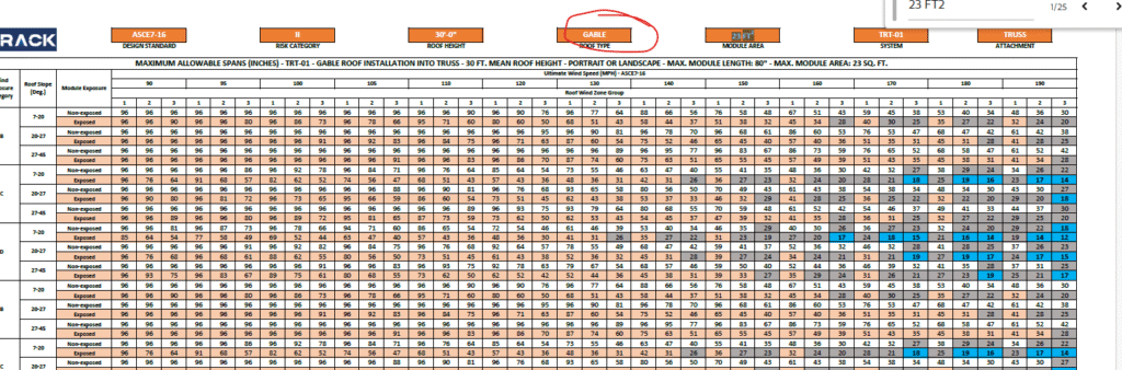
Step 2 – Find the Gable Roof Section
And then since our roof type is “Gable” and we just scroll down, and pay attention to “ROOF TYPE” area to find the “GABLE”,
Step 3 – Match All Parameters
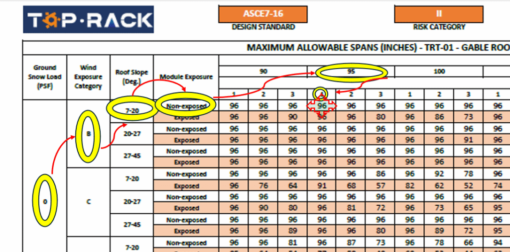
Now match the project details step by step:
- Roof pitch: falls under the 7-20° category
- Roof height: less than 30 ft
- Ground snow load: 0 PSF
- Wind speed: 95 mph
- Wind exposure: Category B (urban/suburban)
- Module exposure: Non-exposed
- Installation zone: Zone 1 (panels installed toward the center, away from edges and ridges)
When we follow these conditions across the table, we reach the maximum allowed span.
Result:
The maximum allowable span is 96 inches.
Since the solar panel width is 44.1 inches, and the maximum allowable span is 96 inches, the TRT 01 Rail-less System can be installed.
Installing on a HIP Roof
If the same project were installed on a Hip roof, the installer should remain in the same 23 ft² table and scroll to the HIP section. All other parameters stay the same.
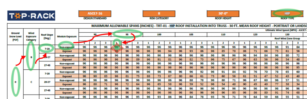
The method does not change; only the roof-type section changes.
For both above situations, since the Maximum Span between brackets (Base) are larger than the solar panel width, the TRT 01 Rail-less system can be installed.
Example: TRT 02 Rail Base or TRT 03 Tile Hook System
The TRT 02 system includes rails, which means bracket spacing can be adjusted depending on the conditions. The goal is still the same: ensure the spacing does not exceed the value listed in the span table.
Project Information
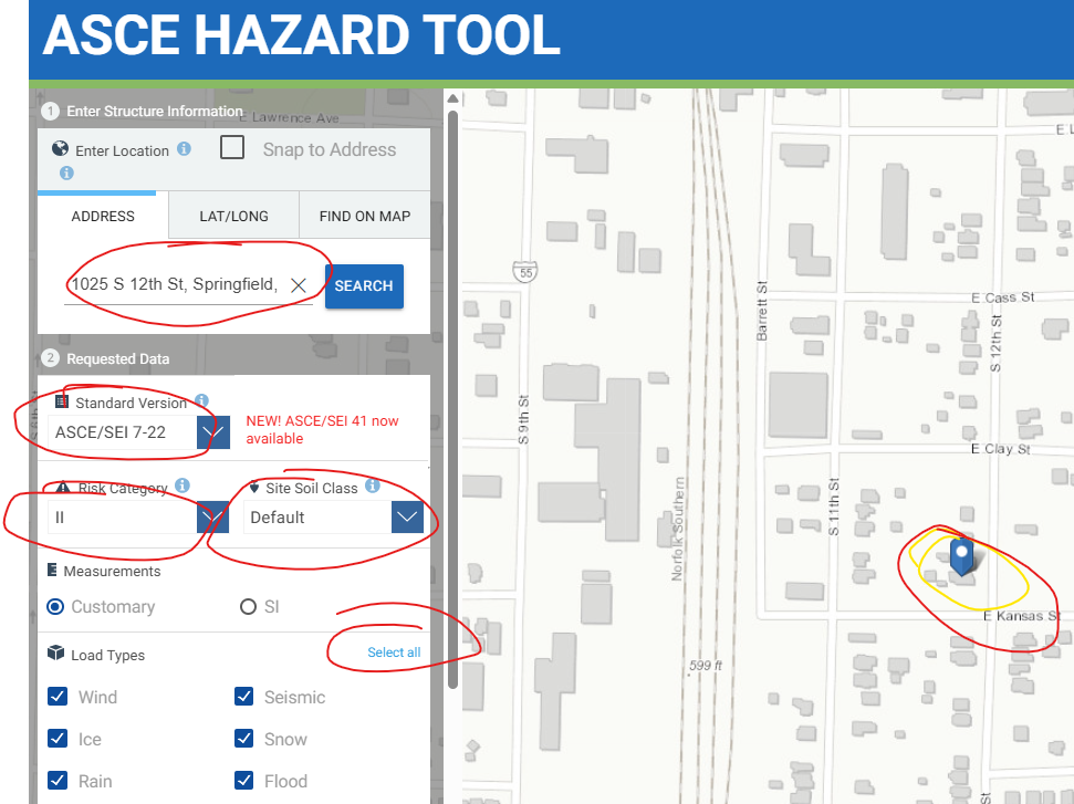
- Location: 1025 S 12th St, Springfield, IL 62703
- Roof Type: Gable roof
- Mounting Method: Truss
- Roof Pitch: Between 18.4-33.7 degrees (using 18.4 degrees as conservative)
- Module: Q.PEAK DUO BLK ML-G10+ 415 (20.73 ft²)
- Product: TRT 02 Rail Base
- Code Used in Illinois: ASCE 7-22
- Hazard Values:
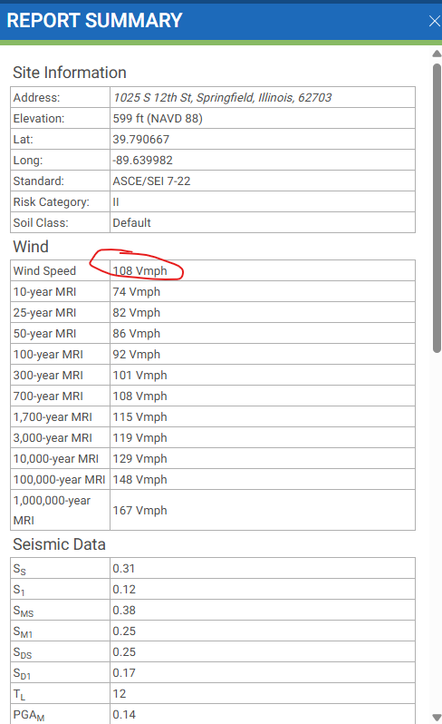
- Wind speed: 108 mph
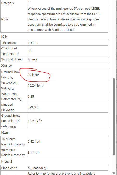
- Ground snow load: 27 PSF
Step 1 – Open the ASCE 7-22 TRT-02 Span Table
Search “23 FT²” again, since the module area still falls in this range.
For safety, choose the 30 PSF snow-load category because it is higher than 27 PSF.
Step 2 – Match All Parameters
- Snow load: 30 PSF
- Roof slope: 7-20°
- Exposure category: B
- Module exposure: Non-exposed
- Wind: use the 110 mph column
- Zone: 1
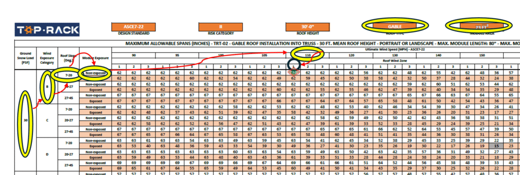
Result:
Maximum allowable spacing = 62 inches
(Installer typically chooses 48 inches based on common truss spacing.)
OSB Attachment Example
If the installer wants to install the bracket on OSB board, then it needs to find the OSB board attachment method page and keep other parameters same and find the correct maximum span, see below:
From this scenario reference, you can see the maximum span for the bracket to be mounted on the OSB board is 27inch, so we will need more brackets to support the load compared to the scenario that we mounted to the truss (rafter).

Result:
Maximum allowable spacing for OSB = 27 inches, meaning more brackets are required.
Conclusion
For all TRT systems, the spacing between brackets is determined only by the Span Table.
The installer must match every parameter carefully, module area, roof type, roof slope, exposure, snow load, and wind speed, and must always pick the conservative option. Installation is acceptable only when the span is equal to or greater than the panel width and within the listed maximum values.