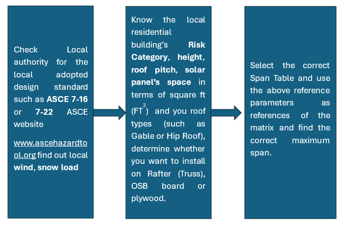
Guide 2 explains how the installation site information collected in Part 1: Installation Site Preparation is applied to the official SPAN TABLES.
The purpose of this guide is to help installers follow the table structure in the correct order so they can perform accurate span table selection and locate the allowable maximum distance between two Bracket (Base) positions using only the published data.
No values should ever be estimated or interpolated outside the tables.
2.1 Selecting the Correct Table Series
Before checking any span value, identify which ASCE 7 edition has been adopted by the local authority.
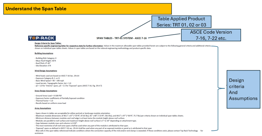
The span tables are provided in two versions, ASCE 7-16 and ASCE 7-22 and these editions use different wind and snow design assumptions. Because the numerical values depend directly on the selected code, mixing them is not allowed.
Once the correct ASCE version is confirmed, continue using that series only. This ensures the maximum span you reference is based on the correct design loads.
2.2 Choosing the Correct TRT System Table
After confirming the ASCE edition, select the SPAN TABLE that matches the TRT system being installed.
The TRT 01 Rail-less System, TRT 02 Rail Base System, and TRT 03 Tile Hook System each have separate structural behaviors and tested limits.
A span value from one system cannot be used for another. Always verify the document title so that both the ASCE code and the system type match your installation conditions before proceeding.
2.3 Understanding Table Structure and Logic
The span tables follow a structured hierarchy.
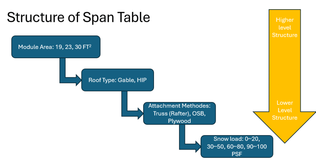
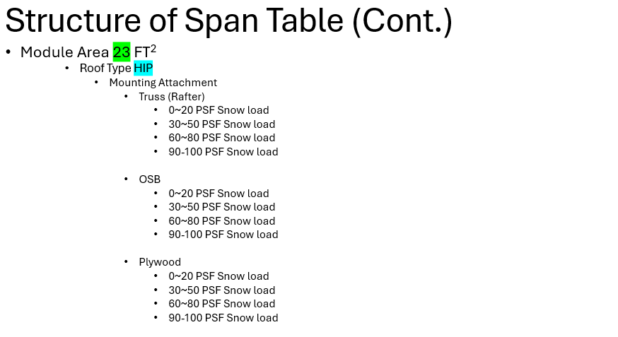
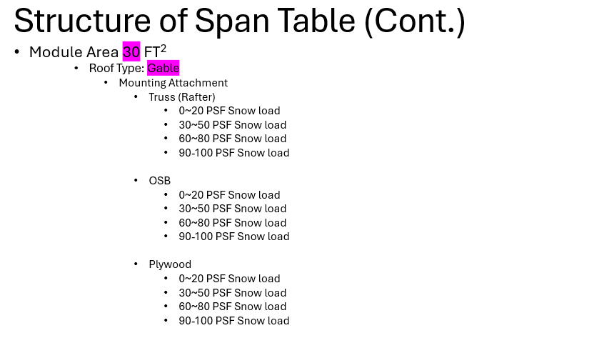
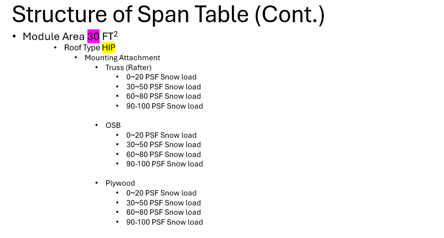
In the span table hierarchy, the lowest-level category is the snow load, typically grouped as 0-20, 30-50, 60-80, and 90-100 PSF.
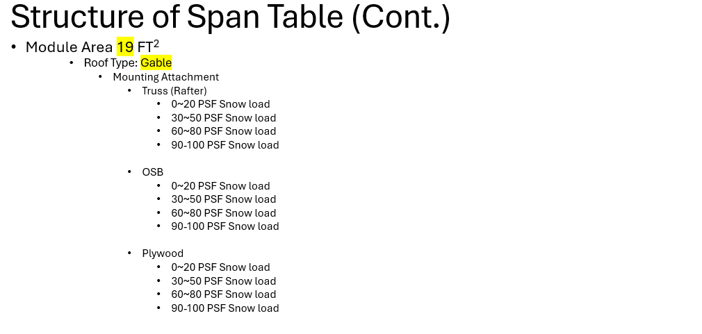
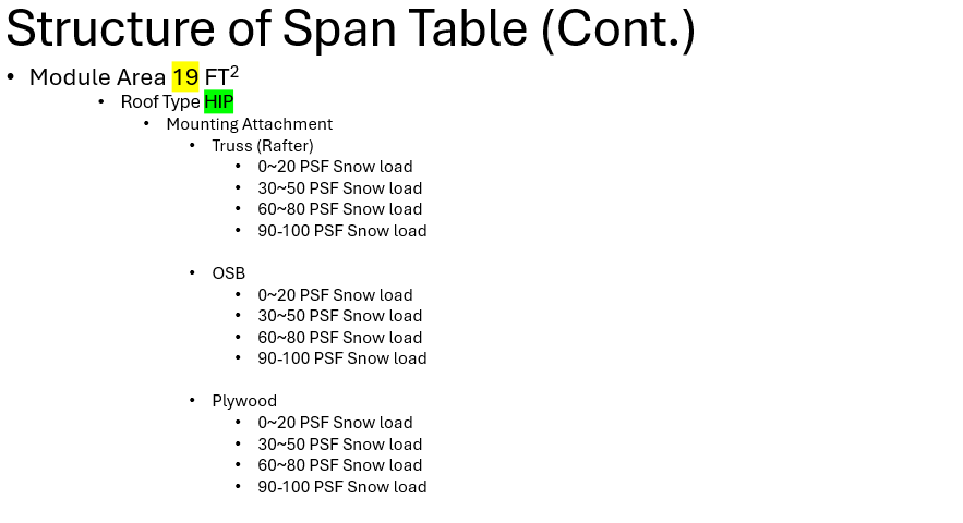
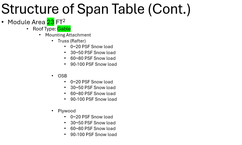
Above snow load, the tables are grouped by attachment method (Truss, OSB, Plywood), then by roof type (Gable or Hip), and at the highest level by module area (for example 19, 23, or 30 FT²).
When you use the table, begin by locating the snow-load band that matches the project conditions shown in the table. Then narrow down by attachment method and roof type, and finally confirm that you are in the module-area group that corresponds to your panel’s area as shown in the tables.
2.4 Using Project Parameters to Find the Span
Once inside the correct table block, match the remaining project data to locate the span value. Follow the row for the correct roof pitch and roof height.
Move horizontally to the wind exposure category, and then align with the design wind speed. The cell where these parameters intersect is the maximum allowable spacing between two Bracket (Base) positions.
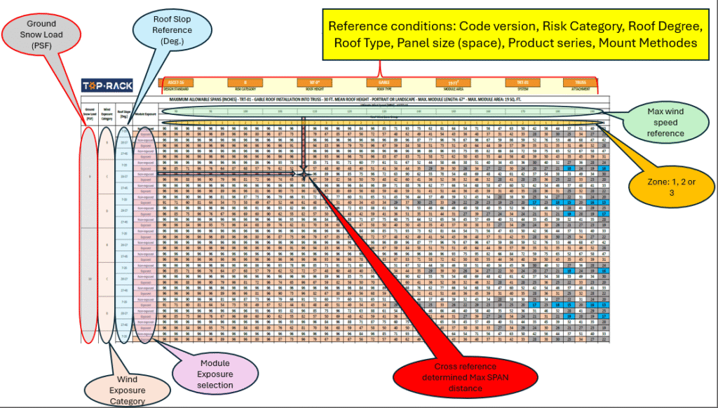
Actual installations must remain at or below this value.
2.5 Design Limits and Safety
Use only the printed values in the tables.
If a project falls between two conditions, choose the more conservative one, higher snow load, higher wind speed, or shorter maximum span.
Do not extend trends or average values. If a required condition is not shown in the tables, treat it as outside the approved range and seek additional guidance from a licensed PE.