1: Preparation
Before determining the maximum distance between each Bracket (Base), it is essential to prepare accurate Installation Site Information.
Every value collected at this stage, local design code, wind and snow data, roof type, and attachment condition, directly informs bracket span preparation and the reference you will later make to the official SPAN TABLES for TRT 01 Rail-less System, TRT 02 Rail Base System, and TRT 03 Tile Hook System.
Completing this preparation ensures that the installation will comply with the proper ASCE 7 series and achieve safe, verified spacing.
a) How to get Installation Site Information
Begin by checking the local building department to find out which ASCE 7 series code has been officially adopted in your area.
Some regions still reference ASCE 7-10, while most have transitioned to ASCE 7-16 or ASCE 7-22.
Confirming the adopted code is mandatory before consulting any table, since the wind-load and snow-load design criteria differ between editions.
You may also ask an AHJ (Authority Having Jurisdiction) officer or a local professional engineer to verify the project’s Risk Category and Site Soil Class.
These two factors are required when generating hazard data and will appear in the inputs of the ASCE Hazard Tool.
Then they can go to the following website www.ascehazardtool.org to find out their local weather hazard information.
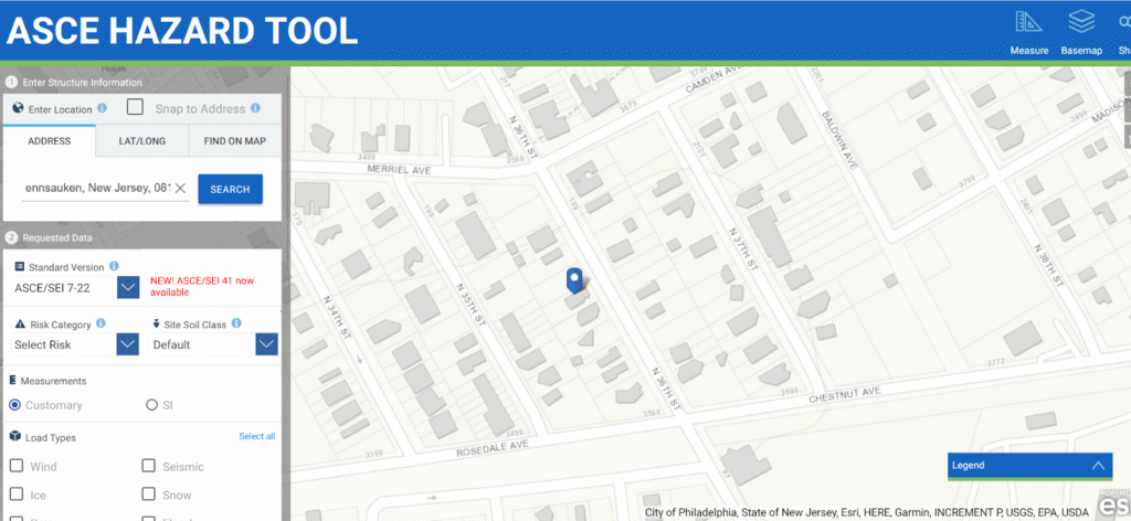
Input your installation site address, and relative Risk Category and Site Soil Class.
Choose the load types you want to evaluate and click View Results to display the local wind and snow parameters.
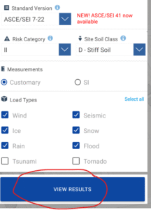
Next you will see details of each load type displayed on the screen, including Wind, Seismic, Ice, Snow, Rain, and Flood.
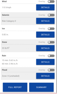
You can use this information for the TRT BOM Generation Tool or as a reference when using TRT 01, TRT 02, or TRT 03 span tables under ASCE 7-16 or ASCE 7-22.
This data will form the foundation for calculating the maximum spacing between brackets.
b) Knowing the Terminology
Before checking the span table, familiarize yourself with the terminology used throughout the design guide.
Roof Types (Shapes)
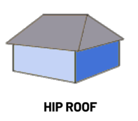
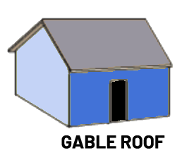
Gable and Hip roofs are the two majority roof types for residential buildings.
Flat roofs are not covered under this instruction and do not fit the TRT 01 / 02 / 03 product series.
Understanding the roof geometry is necessary because the pressure zones and bracket layout vary between these shapes.
Roofing Materials
Shingle (Asphalt shingle, composition shingle etc.):
See below the photo as examples. It is mainly made using asphalt; detailed shapes and colors may vary.
Tile:
There are clay tiles or compound-tile materials, but here they are categorized by shape: S shape, W shape, and Flat shape.

Metal Roof:
There are different shapes of metal roof, such as corrugated and standing-seam, but these are not covered by this instruction since TRT 01, 02 and 03 are not designed for metal roof applications.

Rafter (Truss)
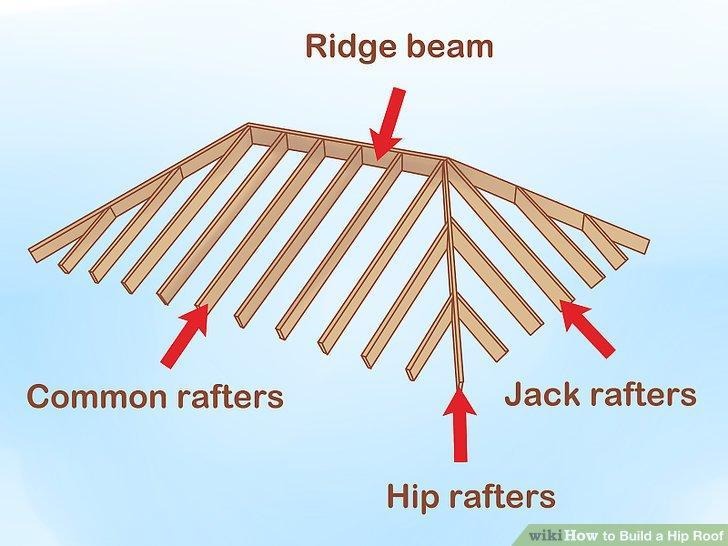
This illustration helps installers visualize the placement of the Bracket (Base) when attached directly to structural members.
Recognizing rafter direction and spacing assists in aligning brackets consistently with structural load paths.
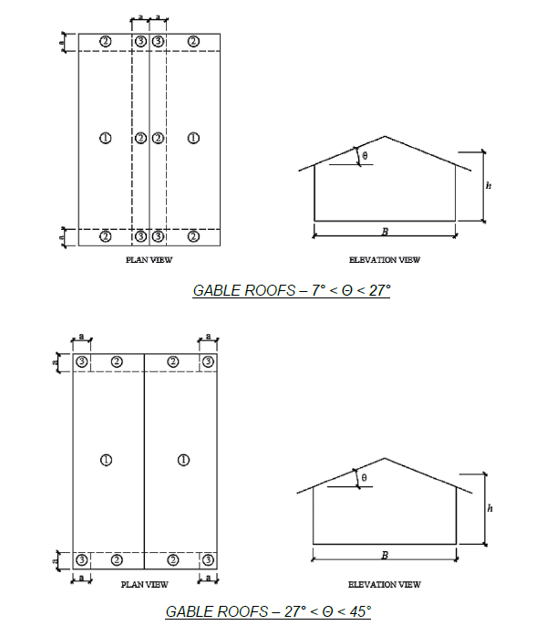
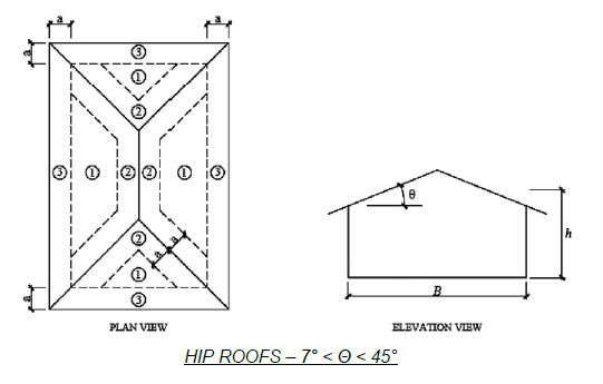
Zones 1, 2 and 3 ( and Zone 4 – Ridge )
ASCE 7 defines several zones on a roof based on wind pressure distribution:
- Zone 1: Main field area of the roof, usually the lowest wind pressure.
- Zone 2: Adjacent to edges, with moderate pressure increase.
- Zone 3: Corners of the roof, experiencing the highest suction pressure due to wind flow separation.
- Zone 4: The ridge (peak) line, where pressure varies with roof shape and pitch.
The extent and width of each zone depend on the building’s dimensions, roof slope, height, and exposure category.
Identifying the correct zone ensures accurate placement and spacing of brackets according to structural loads.
For ASCE 7-16, the zones for the two main roof types are shown below.
For ASCE 7-22, the zone definition has been updated; refer to the diagram below for the current layout.
Attachment Type
The attachment type identifies where the Bracket (Base) will be installed:
- Truss (Rafter): Bracket (Base) installed on Truss (Rafter)
- OSB: Bracket (Base) installed on OSB board
- Plywood: Bracket (Base) installed on Plywood
Each attachment surface differs in stiffness and load resistance, influencing the allowable span shown in the tables.
Module Area (FT²)
This refers to the surface area of a solar module.
You should always make sure the table you picked in the module area is larger than your real solar panel area.
2, What Table That We Provided
We provide two sets of SPAN TABLES for each of the TRT 01, TRT 02, and TRT 03 systems. Select the series that matches the locally adopted ASCE 7 design code.
ASCE 7-16 SERIES:
- SPAN TABLES – TRT-01 SYSTEM – ASCE 7-16.PDF
- SPAN TABLES – TRT-02 SYSTEM – ASCE 7-16.PDF
- SPAN TABLES – TRT-03 SYSTEM – ASCE 7-16.PDF
ASCE 7-22 SERIES:
- SPAN TABLES – TRT-01 SYSTEM – ASCE 7-22.PDF
- SPAN TABLES – TRT-02 SYSTEM – ASCE 7-22.PDF
- SPAN TABLES – TRT-03 SYSTEM – ASCE 7-22.PDF
You need to refer to your local adopted design code and then use the matching series to find the maximum distance between two Bracket (Base) locations. Proceed to Guide 2 – Choosing and Understanding Your SPAN Table for the selection steps.
Summary of Preparation
Before referencing any span table, make sure you have confirmed:
- Adopted design code (ASCE 7-10, 7-16, or 7-22)
- Risk Category and Site Soil Class
- Wind and Snow load values from www.ascehazardtool.org
- Roof Type, Roofing Material, and Attachment Method
- Correct Zone classification (1 – 4)
- Module Area, Roof Pitch, and Roof Height
These parameters are essential inputs for the ASCE 7-16 SERIES or ASCE 7-22 SERIES SPAN TABLES supplied for TRT 01, TRT 02, and TRT 03.
Accurate preparation minimizes design error, improves safety, and ensures code compliance during installation.
Next Step
Once the installation site information is collected and verified, proceed to Guide 2 – Choosing and Understanding Your SPAN Table.
That guide will show how to apply these parameters to locate the correct page and determine the maximum spacing between two Bracket (Base) positions according to the selected system.